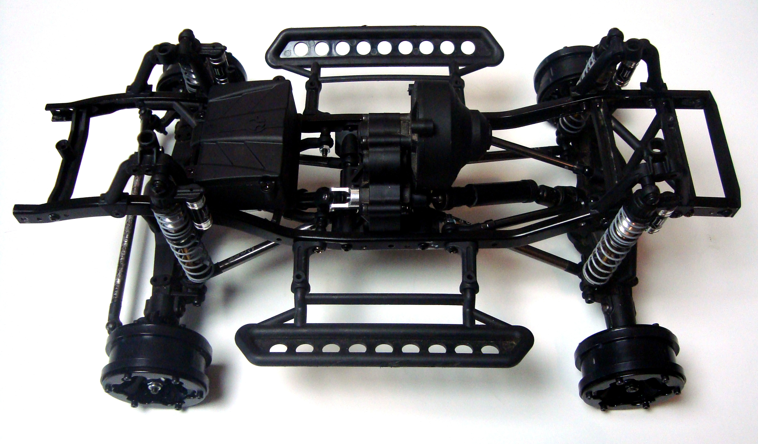
In part 2 I had shortened the standard Axial wheelbase by relocating the stock shock towers and adjusting the link length to match which left the wheelbase at 25cm but the body was listed as having a 24cm wheelbase. The body arrived this week and the wheelbase dimensions listed online were correct. This meant that I had to find a way to shorten the wheelbase by 1cm.
I could have made a bracket to mount to the three holes on the shock tower but this felt like it would be a band-aid type fix rather than a properly designed approach. So I decided to move the rear shock tower forward by drilling a few new holes. The distance that I had to move it forward required that one leg of the tower be mounted on the downward angle of the rear section of the chassis which meant that I had to change the towers to the front version which have a downward angle built in. So Project Shorty is now running 4 front shock towers. This gives the required wheelbase while still maintaining a basically vertical shock orientation. Moving the shock towers forward gave me additional mounting options as well which I wouldn't have had if I had simply created a bracket to hang off of the previous location.
The Links
Next up were the new links. In part 2 I had used 3mm threaded rod to create temporary links to figure out the correct length. Once I had done that I took measurements and cut the corresponding stock gray SCX10 links to match. There was only one small wrinkle to having such a short wheelbase. The stock 3-link has a "Y" bracket that mounts to the front axle to create the upper link mounts. That "Y" shape has a fixed angle and for such short links it was too narrow for them to reach out to the frame rails. So for the frame mounting points on the front upper links I had to space them inward with some spacers and longer screws. The rear is using a 4-link configuration so no spacers were needed.
The Driveshafts
With the links done it was time to move on to the driveshafts. The donor chassis came with the Axial WB8 driveshafts. I started with the rear as that was the longer of the two and slowly shortened it until it fit in the space. This however left another problem, it was binding under full droop, when the suspension was under no compression. The solution was to clock the axle slightly upward by adding a short spacer on the upper links. I then moved on to the front driveshaft, which was even shorter, again cutting slowly until I got down to a size that would fit in the space. And again it was binding under full droop. However in this case there was no way I could clock the axle because doing so would put the axle at such a steep angle that there would be virtually no steering angle and the steering arm up front would nearly drag on the ground. So unfortunately I had to put aside the now cut down WB8 driveshaft and dig through the spares bin. I found a lightly used RC4WD Punisher shaft that worked perfectly as it has a different type of universal joint on each end which has more articulation angle than the WB8 shafts do. I again cut this shaft to length and now the shafts spin without binding.
Conclusion
So now Project Shorty is a roller and it seems like everything is on track but there's one major problem. I want to have a full interior on this build and the Axial transmission and the motor sit exactly where the driver should be. I was hoping that they would have been back a bit further in the body so I could hide them inside the vertical part of the seat or something similar but no luck in this case. What is the solution? Well I've become so frustrated with this problem from back in the days of my Tundra that I've decided to start working on a 3D printed motor /trans mount as well as a new center transfer case design. I don't have a lot of time though as Project Shorty is meant to be a gift and the deadline is fast approaching. Wish me luck!


Comment here
You must be logged in to post a comment.